Transmission photoelasticity method
Same as other methods, the technique is based on birefringence properties of materials, where there exist several indexes of reflection, associated with the wave polarization direction. Birefringes reveal when the material is subject to anisotropic stress. In other words, the refractive index depends on the eigenvalues of the local stress tensor. In this method, the light passes through the particles and is recorded on the other side to see birefringence. This method has been utilized in experiments for several decades.
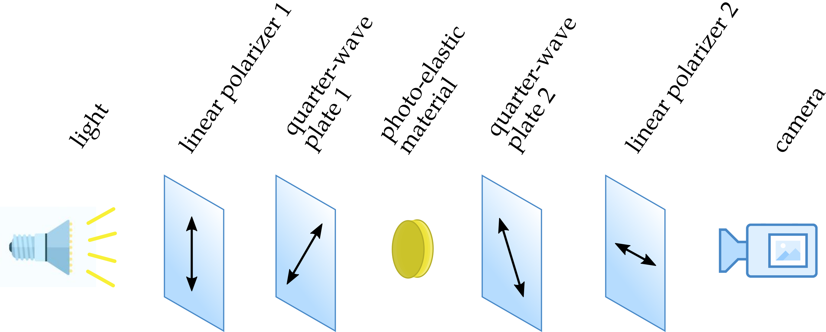
Photo-elasticity is best observed using circularly polarized light. Circularly polarized light is a composition of two orthogonal linearly polarized waves with a quarter-wave phase shift. As shown in the figure below, this polarization can be obtained by passing unpolarized light through a specific combination of linear polarizer and quarter-wave plate. On the other side, covering the camera sits another circular polarizer with opposite polarity, which blocks the unperturbed light. If there exists a photo-elastic material in between under anisotropic stress, the wave components, polarized in the principal directions of the local stress tensor, travel at different speeds. This speed difference results in phase shifts in the components of the wave and changes circularly polarized light into elliptical one. The part of the wave subject to this change is passed through the second circular polarizer and is recorded by the camera.
For detailed wave equations look at this section.
- The photo-elastic technique: The combination of linear polarizer 1 and quarter-wave plate 1, with 45 degrees difference in principle directions, turns unpolarized white light into circularly polarized light passing through the photo-elastic material. The second combination of polarizer and plate creates a circular polarizer with opposite polarity, blocking the unperturbed light. In the case of local anisotropic stress in the photo-elastic material, there will be different phase shifts for different components of the light polarization. These phase shifts perturb the polarity of the wave, causing the light to be observed by the camera. Arrows represent polarization directions:
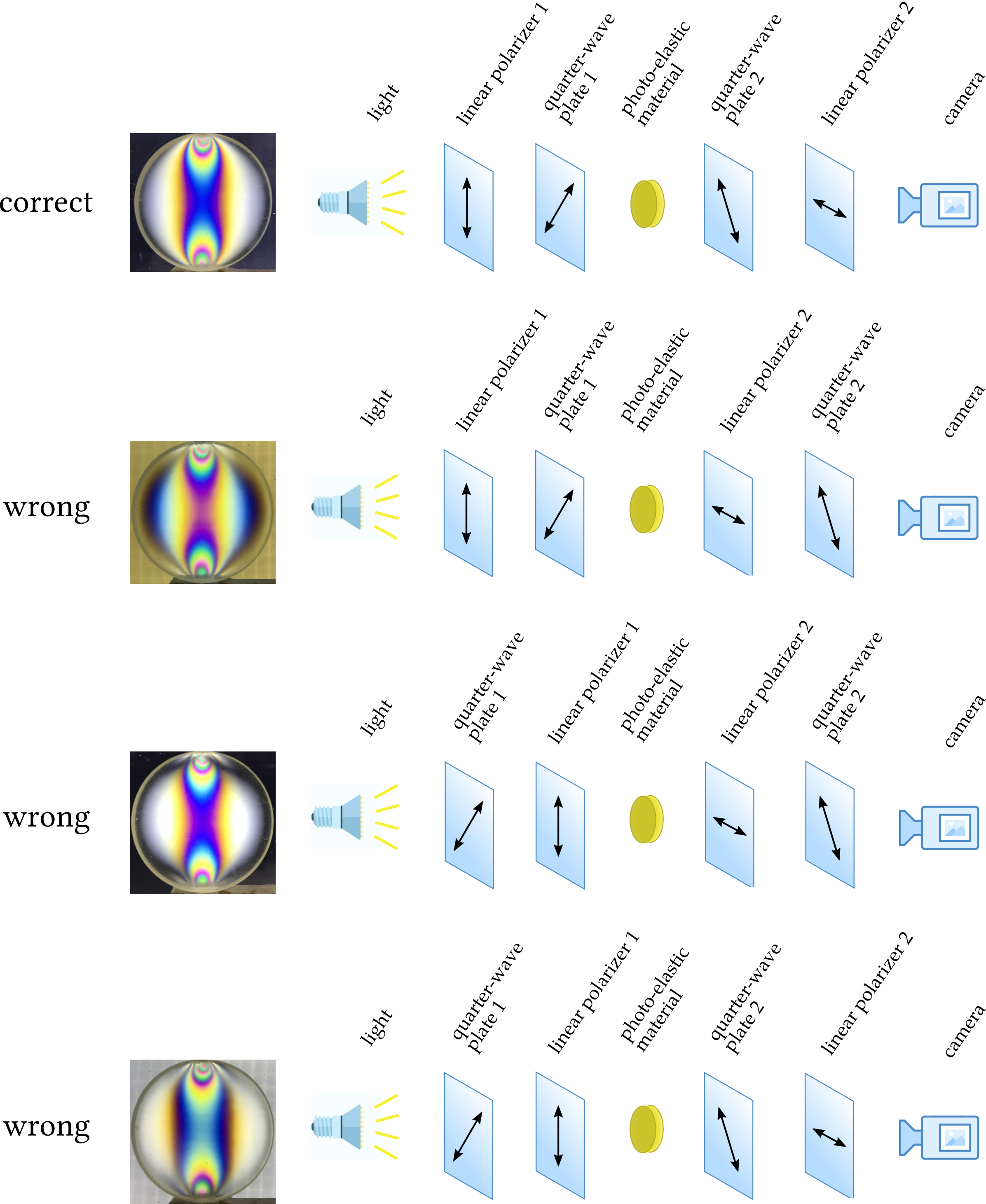
While constructing the optical system with a pair of crossed polarizers, it is extremely crucial to have them aligned the exact same way as illustrated in the image above in order to obtain the correct photo-elastic response from the stressed material. There are two ways to obtain circular polarizers: (1) purchase linear polarizers and quarter-wave plates and align the polarization axes and fast axes as shown in the figure above; (2) purchase circular polarizers, which are pre-aligned linear polarizers with quarter-wave plates combined together, and make sure light passes these two polarizers in the correct order. For the second method, due to two sides of the circular polarizer being almost indistinguishable, it is common to accidentally flip one or two of the circular polarizers, which will result in the wrong polarized image for analysis. A nice and easy way to figure out the linear polarizer side and quarter-wave plate side can be referred to this session. The following figure shows examples of photo-elastic responses from correct and wrong polarizer arrangements in the second method.
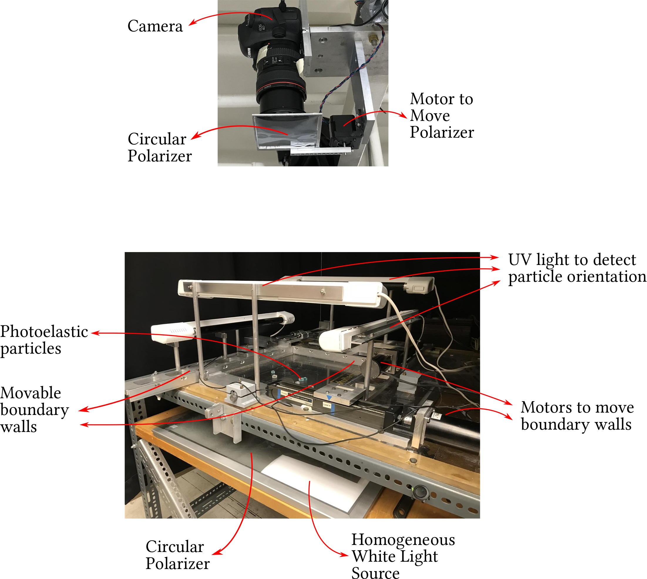
And below shows a setup that has been designed for containing a system of photoelastic grains in a rectangular/square box and applying pure shear (compression in one direction and dilation in the other), uni-axial compression, and bi-axial compression.
[