Photoelasticity: theoretical aspects
This wiki is dedicated to the use of photoelasticity in a general manner. Before going more into detail about how to make photoelastic samples, how to image them, and even how to get quantitative information from photoelasticity, it is important to begin by some physical explanations about this phenomenon. The goal is not here to go deep into details. For those who would like more information, we suggest you to read the excellent wikipedia page about photoelasticity or this very nice lecture by W. Wang.
The photoelastic phenomenon is based on the birefringence properties of some transparent materials. In a birefringent material, the speed of light, and consequently the index of refraction depends on wave polarization. In other cases, such as glass and polymeric materials, birefringence arises only when the material is subject to anisotropic stress. In other words, the refractive indexes depend on the eigenvalues of the local stress tensor. This phenomenon is called photoelasticity and has been utilized in experimental science for several decades.
Using photoelasticity, we can measure internal stress. This measurement is best performed using circularly polarized light, which provides isotropic polarization. Circularly polarized light is a composition of two orthogonal linearly polarized waves with a quarter-wave phase shift. As shown in the figure below, this polarization can be obtained by passing unpolarized light through a linear polarizer and a quarter-wave plate. The quarter-wave plate creates a phase shift between two orthogonal components of the light polarization. Passing unpolarized light through the combination of linear polarizer and quarter-wave, as shown in the figure, results in circularly polarized light. On the other side, covering the camera sits another circular polarizer with opposite polarity, which blocks the unperturbed light. If there exists a photoelastic material in between under anisotropic stress, the wave components, polarized in the principles directions of the local stress tensor, travel at different speeds. This speed difference results in phase shifts in the components of the wave and changes circularly polarized light to elliptical. Consequently, a part of the wave subject to this change is not completely blocked by the second circular polarizer and is passed through it, recorded by the camera.
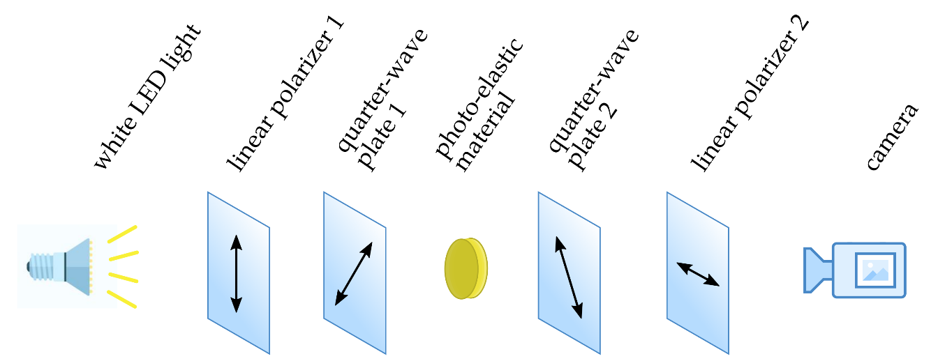
The photoelastic technique: The combination of linear polarizer 1 and quarter-wave plate 1, with 45 degrees difference in principle directions, turns unpolarized white light into circularly polarized light passing through the photoelastic material. The second combination of polarizer and plate creates a circular polarizer with opposite polarity, blocking the unperturbed light. In the case of local anisotropic stress in the photoelastic material, there will be different phase shifts for different components of the light polarization. These phase shifts perturb the polarity of the wave, causing the light to be observed by the camera.
Photoelasticity can be used to quantitatively measure local stress. Assuming that the relation between stress and refractive index is linear:
where is an eigenvalue of the local stress tensor, is the refractive index for polarized light in the corresponding direction, and is called the stress-optical coefficient. The relative phase shift of wave components in the eigen-directions of local stress tensor can be calculated using:
where is the wavelength of the light and is the distance traveled inside the material, which corresponds with the sample stiffness. Given this phase shift, the intensity of the emergent wave is:
This equation relates internal stress and intensity for a single wavelength. In most cases, both the light and camera channels cover a wide range of wavelengths. Stress calculation is less noisy using a narrow range of wavelengths and a single channel from the camera. However, it is still possible to retrieve stresses using white light.
The last equation makes it possible to invert the mechanical problem and to get the full stress field (even if there is non-uniqueness of the solution). This is not a trivial problem but in this wiki we show how to do it in the specific case of loaded discs. Other more qualitative possibilities exists to have an estimation of the stress field.
[