Terahertz photoelasticimetry
As powerful as the technique of imaging photoelasticity is for mapping strain fields, one of its strengths also represents one of its limitations: its two-dimensionality. By using crossed polarizers to image strain through optical birefringence in irregular arrays of squeezed photoelastic samples, maps of strain fields may be easily and compellingly recorded. However, for many different applications and scientific purposes, we wanted to go beyond this and explore techniques for imaging strain fields in three dimensions, not just two. Holography represents a possible approach toward three-dimensional imaging of strain birefringence, but the photoelastic materials that best exhibit optical birefringence have only limited optical translucence. Consequently, it would have been difficult to achieve three-dimensional holographic reconstructions of three-dimensional strain fields using visible wavelength techniques.
However, many photoelastic materials are much more translucent at longer wavelengths, so the possibility of imaging strain birefringence at terahertz frequencies could overcome this limitation. Terahertz holographic imaging has recently been demonstrated [1-6], so the opportunity is ripe to combine techniques. Although early measurements confirmed the translucence of photoelastic materials at terahertz frequencies, first attempts at measuring strain birefringence failed, for a simple reason. The physical mechanism responsible for strain birefringence is the microscopic displacement of atoms from their equilibrium position in response to stress, a displacement sufficient to change the cross-polarimetric response of the material. To produce a detectible cross-polarimetric signature, this atomic displacement must be comparable to the wavelength of the affected radiation. Although such atomic displacements are typically only a fraction of a nanometer, such cross-polarimetric signatures are still detectable for optical illumination, whose wavelengths are hundreds of nanometers. However, typical wavelengths of terahertz radiation are hundreds of microns, much too large to be affected by the atomic displacements in standard birefringent materials.
An alternative approach would be to develop a metamaterial whose meta-atoms are much larger and can exhibit much greater displacements [7]. As with optical measurements of stress birefringence in photoelastic materials, such terahertz metamaterials may be measured between crossed polarizers when illuminated from above by an illuminator at the appropriate terahertz resonance frequency. At the current time, there is no satisfactory equivalent to a focal plane array charge-coupled device (CCD) camera at terahertz frequencies, so the optical camera must be replaced by a single-element detector or a few-element detector array that is raster scanned behind the second polarizer to reconstruct the cross-polarimetric image.
A number of micron- or millimeter-sized meta-atom geometries may be conceived for the synthetic terahertz photoelastic metamaterial, but the basic criterion is that the symmetry of the meta-atom changes when stress is applied (Figure X). When stretched or stressed, an array of elastic meta-atoms on an elastic substrate might distort from circular to elliptical, for example, or from square to rectangular, all while maintaining transparency. For such a material to be used for non-destructive investigations of strain fields, it is essential that these elastic meta-atoms function like true atoms by reversibly returning to equilibrium when stress is relieved. In other words, they must not be stretched beyond their deformation limit. An illustration of such a metamaterial with cross-shaped gold meta-atoms, the length of whose horizontal arms is equal to the vertical arms when stretched but buckle and shrink when relaxed, is presented in Figure Xe.
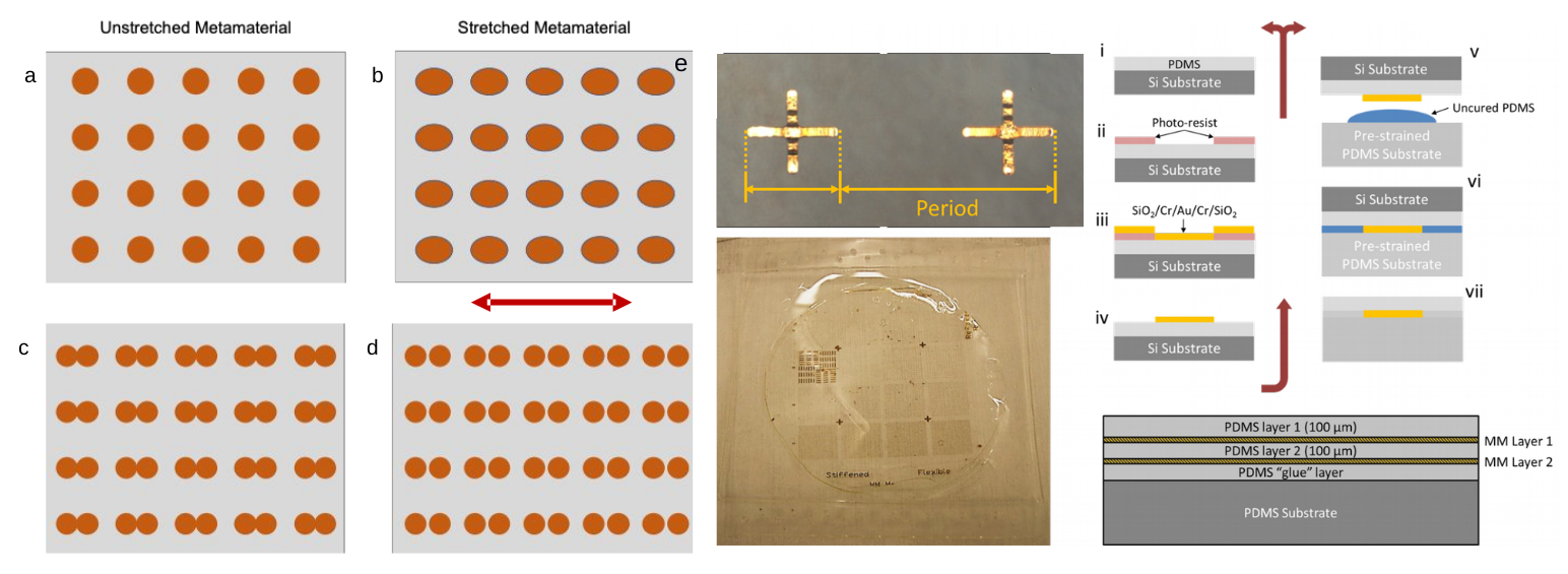
Figure X: Conceptual illustrations of metamaterials exhibiting terahertz frequency strain birefringence using reversible, elastic meta-atoms (a,b) or non-reversible, rigid meta-dimers (c,d). (e) An illustration of a stretched bi-layer terahertz birefringent metamaterial composed of semi-rigid cross-shaped meta-atoms whose arms buckle when the metamaterial is relaxed. Also shown is a photograph of such a metamaterial and an illustration of the fabrication methodology.
Alternatively, an array of rigid, metallic meta-dimers on an elastic substrate might be designed to break in a pre-determined location when stressed, such as a pair of circular or square meta-atoms in a barbell configuration with a weak break junction joining them. Such a metamaterial will be much easier to construct, but unless the break junction can be healed and good electrical conductivity restored when stress is relieved, it may only be used once for imaging a strain field. This destructive characteristic could actually be an advantage for applications in which it is necessary to record instances of extreme stress at some moment in the past. If this meta-dimer array is distributed within a composite material, terahertz polarimetric imaging could easily identify locations where stress above a certain threshold had occurred. An example of a non-reversible photoelastic strain field, measured using crossed polarizers at the resonance frequency of the terahertz metamaterials on a stretched elastic support, is provided in Figure Y.
A more thorough demonstration of this, inspired by the work of Prof. Behringer, has recently concluded [7]. It used an array of bowtie-shaped meta-dimers to record the strain history of a stretched, visually opaque elastic material. The next logical step would be to construct three-dimensional arrays of reversible or non-reversible meta-atoms in an elastic support. Three-dimensional strain fields may be mapped by modifying terahertz holographic imaging to include crossed-polarizers so that the three-dimensional strain fields may be fully reconstructed in these synthetic photoelastic metamaterials.
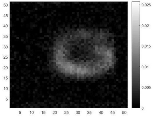
Figure Y. Spatial map of the photoelastic strain measured for an array of bowtie-shaped terahertz metamaterials on an elastic support. The stretched sample was placed between crossed polarizers and raster scanned through a narrow terahertz beam at the resonance frequency that was detected by a single broadband detector. The axis labels are in millimeters, and the grayscale represents the unnormalized cross-polarimetric signal indicating the regions experiencing the greatest strain.
References:
[1] R. J. Mahon, J. A. Murphy, and W. Lanigan, “Digital holography at millimetre wavelengths,” Opt. Commun. 260(2), 469–473 (2006).
[2] A. A. Gorodetsky, and V. G. Bespalov, “THz computational holography process & optimization,” Proc. SPIE 6893, F1–F9 (2008).
[3] Y. Zhang, W. Zhou, X. Wang, Y. Cui, and W. Sun, “Terahertz Digital Holography,” Strain 44(5), 380–385 (2008).
[4] A. Tamminen, J. Ala-Laurinaho, and A.V. Rӓisӓnen, “Indirect holographic imaging: evaluation of image quality at 310 GHz,” Proc. SPIE 7670, A1–A11 (2010).
[5] A. A. Gorodetsky, and V. G. Bespalov, “THz pulse time-domain holography,” Proc. SPIE 7601, 71–76 (2010).
[6] M. Heimbeck, M. Kim, D. Gregory, and H. O. Everitt, "Terahertz digital holography using angular spectrum and dual wavelength reconstruction methods," Opt. Express 19, 9192-9200 (2011).
[7] H. O. Everitt, T. Tyler, B. D. Caraway, C. M. Bingham, A. Llopis, M. S. Heimbeck, W. J. Padilla, D. R. Smith, N. M. Jokerst, “Strain Sensing with Metamaterial Composites”, Submitted to Adv. Opt. Mater. (2018).
[